Read the Latest News from KJ6ER Antennas
͏ ͏ ͏ ͏ ͏ ͏ ͏ ͏ ͏ ͏ ͏ ͏ ͏ ͏ ͏ ͏ ͏ ͏ ͏ ͏ ͏ ͏ ͏ ͏ ͏ ͏ ͏ ͏ ͏ ͏ ͏ ͏ ͏ ͏ ͏ ͏ ͏ ͏ ͏ ͏ ͏ ͏ ͏ ͏ ͏ ͏ ͏ ͏ ͏ ͏ ͏ ͏ ͏ ͏ ͏ ͏ ͏ ͏ ͏ ͏ ͏ ͏ ͏ ͏ ͏ ͏ ͏ ͏ ͏ ͏ ͏ ͏ ͏ ͏ ͏ ͏
| Introducing the New KJ6ER 2-Element Parasitic PERformerArray Antenna with +3.1 dB gain over a single PERformer Quarterwave Antenna
|
|
|
| |
|
|
| Dear Fellow Portable Antenna Geeks 😀
|
|
|
| |
|
|
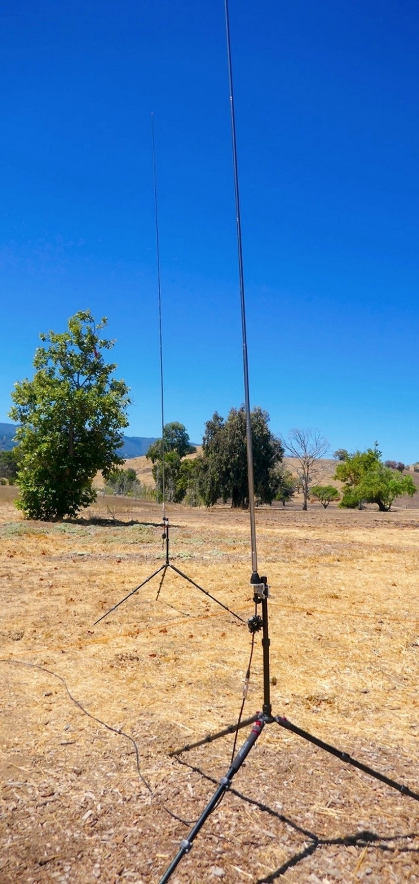
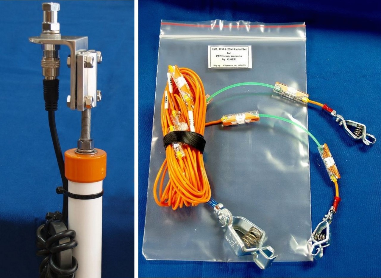
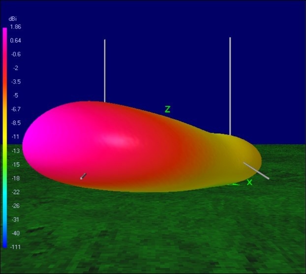
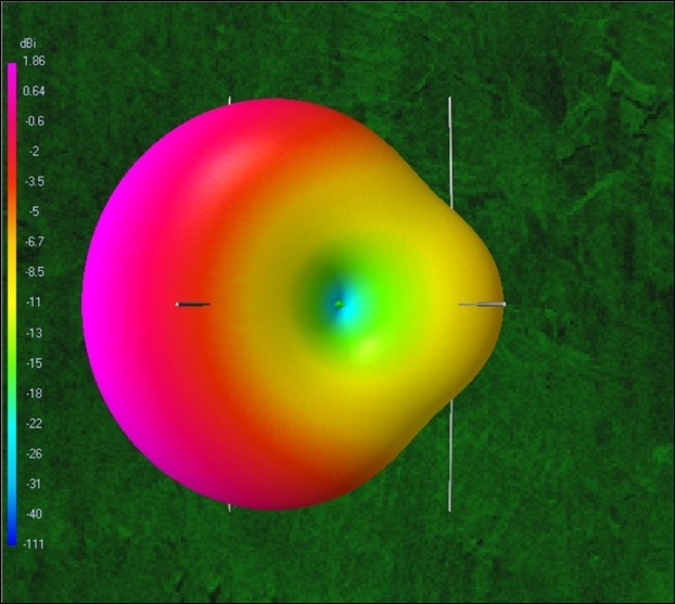
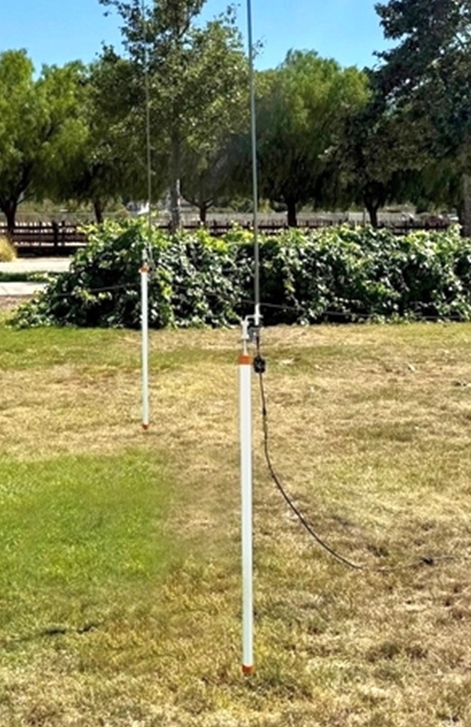
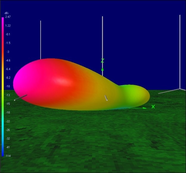
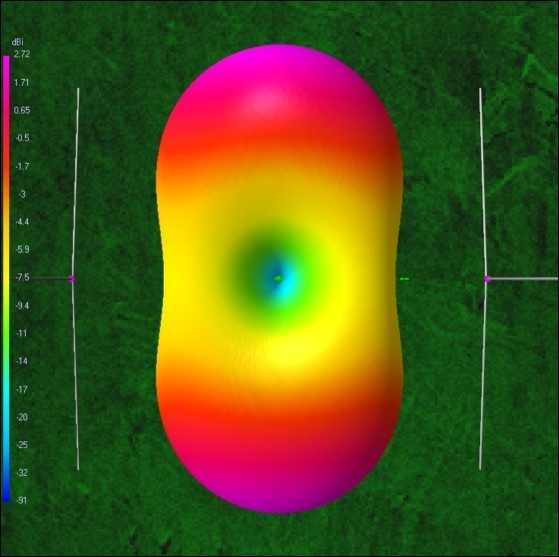
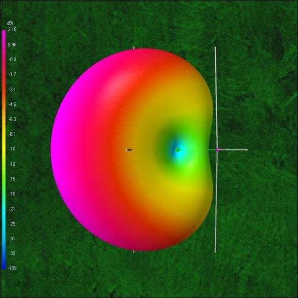
| I am very excited to announce that the ARRL™ QST award-winning KJ6ER PERformer Antenna can now be transformed into a 2-Element Parasitic PERformerArray featuring double the forward gain over a single PERformer antenna and providing significantly increased front-to-back characteristics! As the 11-year solar cycle winds down over the next few years, be prepared to combat it with more radiated power in the field. With the new 7-band, 2-element parasitic array, two omnidirectional PERformer antennas deliver an average of +3.1 dB forward gain over a single PERformer and a 7.7 dB front-to-back ratio for improved signal-to-noise benefits. If you do not have the time or ability to build another PERformer, you can purchase a high quality US-manufactured PVC mount version already assembled with bundled or a la carte options for different elevated radial sets and a new 16" stainless steel spike. More than two dozen PERformers have already been sold during its first month and have received all 5-star reviews from buyers! Consider getting yours today.
|
|
|
| |
|
|
| What is a Parasitic Array? A 2-element parasitic antenna array uses a single driven element (radiator connected to a feedline) and another parasitic element (not connected to a feedline) as a director in front of it, or as a reflector behind it. The electromagnetic field from the radiator energizes the nearby parasitic element by inducing current within it through mutual coupling which, in turn, reradiates the driven element signal both constructively and destructively forming a unidirectional cardioid radiation pattern. Where constructive, the parasitic element reinforces a portion of the forward driven signal for increased gain. Where destructive, it cancels some of the rear driven signal to create a null forming beneficial directivity and front-to-back characteristics. |
|
|
| |
|
|
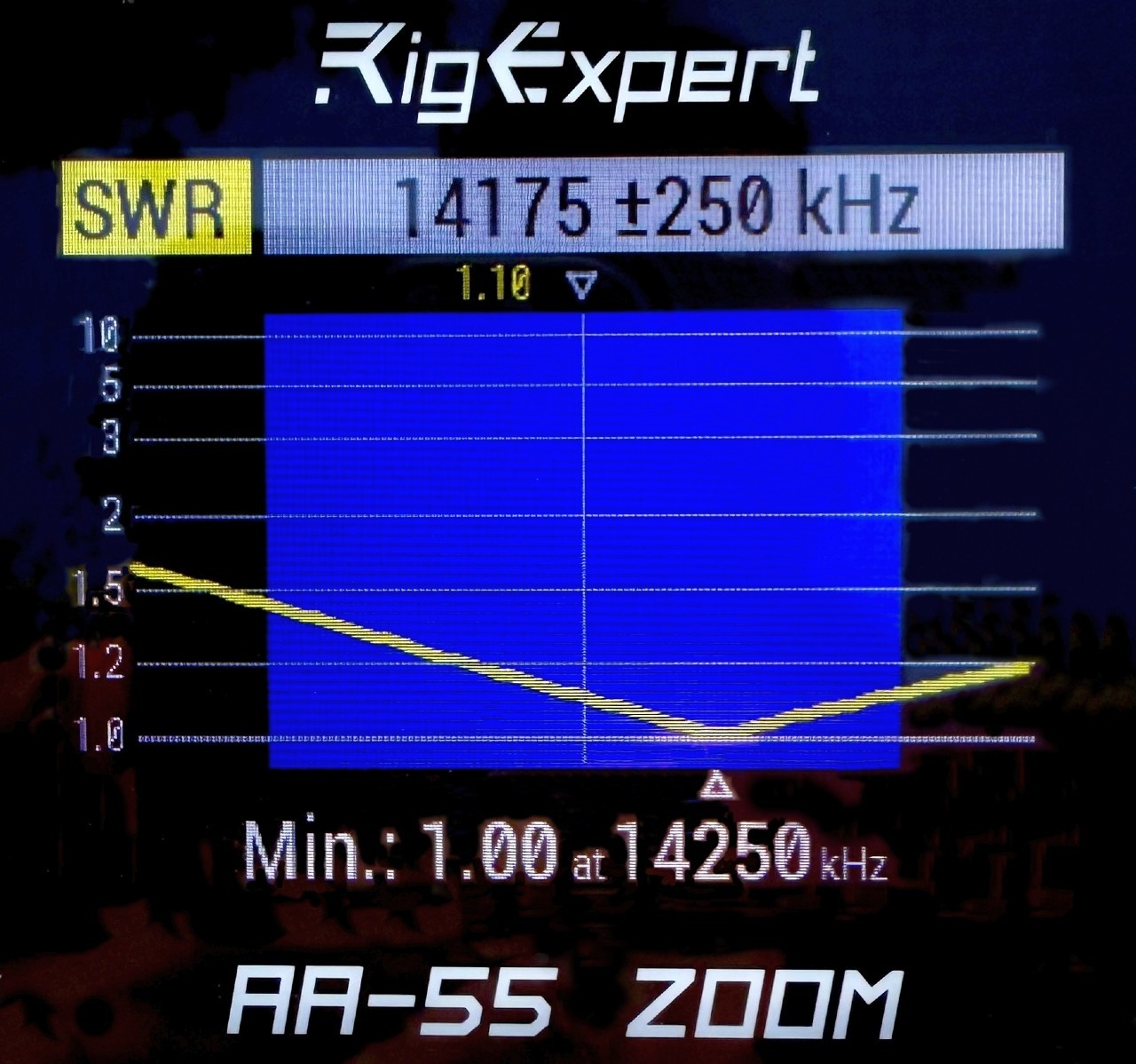
| The new 2- Element Parasitic PERformerArray has been extensively computer-modeled in 4NEC2 to optimize the spacing between the two antennas, as well as their telescoping whip lengths on 40M-6M. The free 15-page PDF plans feature all the design details, radiation charts and deployment tuning process to get your parasitic array up an running easily in the field! I have already used this parasitic array on 20M at several POTA activations recently and was amazed by its performance! From the west coast, I deployed the two PERformers a quarterwave apart and aligned them to a bearing of 60 degrees ENE to radiate across North America. To my surprise, I was receiving S8-S9 signal reports from hunters on the eastern seaboard! For those extra adventurous antenna geeks, the free PDF also explores the design and field deployment of a 3-Element parasitic PERformer array leveraging both a reflector and a director. It features +0.6 dB more gain than a 2-element but, more significantly, it provides +3.7 dB more front-to-back and +4.5 dB more front-to-side for greater signal-to-noise benefits! Of course, it requires 3 omnidirectional PERformer antennas with the center one fed by coax surrounded by a longer reflector behind it and a shorter director in front of it.
|
|
|
| |
|
|
| What's Coming - In October, I will be sharing a new free PDF with plans for a 2-element Phased PERformerArray that will also require two PERformer antennas but as a phased array, where both identical antennas will be fed by coax with a special phasing delay line to one of the elements. By delaying the RF energy to one of the antennas, you will be able to control the bidirectional or unidirectional radiation pattern of the array to focus and direct your signal. The Phased PERformerArray will feature more gain and front-to-back than the parasitic but will require special electrical length coax based upon the operating frequency, phasing delay and coax velocity factor. I am currently working with a prominent US-based cable manufacturer to provide these special cables at a good price for builders. Stay tuned for the free PDF plans and even more geeky antenna fun coming soon! |
|
|
| |
|
|
| Until next time, keep having fun out there! Building ham radio antennas is our last homebrewing frontier and I am dedicated to helping you do so successfully! See all my free antenna design plans at the cloud links below. If someone forwarded this email to you and want to be added to my antenna geeks email list, send me a message and you will be the first to receive new KJ6ER antenna designs and updates! I am also available to present my antennas to your Amateur Radio Club via Zoom. Let me know if they are interested! As always, feel free to reach out to me if you ever have any questions, I'd be happy to help you! 🙂 73 KJ6ER, Silicon Valley |
|
|
| |
|
|
| My mission is to design efficient and effective portable antennas for the every-ham that focus on the optimal integration of performance (high radiation efficiency), elegance (speed and simplicity of deployment) and convenience (ease of transport and storage). These designs are always shared for free with the global amateur radio community to encourage more radio operators to homebrew their own portable antennas. |
|
|
| |
|
|